
Prospecton brief: clear marks on small connector shells
The client was an electronics contractor in Prospecton, Durban, working with connector shells used in assembled units going to local and national customers. Their need was practical: polarity marks and part identification had to be applied cleanly, stay in the right position, and remain legible after handling, assembly and field use.
Because connector shells are usually smooth, compact and moulded in repeating shapes, we treated the job as a precision pad printing run rather than a general marking task. The marks had to sit neatly in a limited print area without flooding edges or shifting on curved surfaces. The client was also clear that the finish needed to support their own compliance checks, while they stayed responsible for final device approval and product conformity.
We focus on repeatability, controlled setup and practical production steps that hold up when a customer needs steady output week after week.
What made the job tricky
Connector shells are not forgiving. The print area was small, the surface was moulded plastic, and the parts had to be loaded and unloaded without damaging the fresh print. A mark that looks fine on a sample can become unusable once the line starts moving, so we spent time on setup before any full run was released.
The brief had a few constraints that shaped the process:
- Polarity and part ID had to remain sharply defined on a compact print face.
- The marks needed to align the same way every time on the shell profile.
- Adhesion had to suit repeated handling and assembly contact.
- The run had to support repeat production rather than a once-off sample only.
- The shell geometry called for a fixed holding method, not loose hand placement.
We also had to account for normal South African production realities. That means the process has to be set up with enough control to keep results stable, not just on a calm day but through regular shop-floor conditions.
Artwork, plates and sample approval
We began with artwork preparation and checked the polarity symbols and identification marks against the space available on the shell. Where needed, we cleaned up line weight and spacing so the image would transfer well through the pad without losing detail. The artwork was then used for plate exposure and plate etching, giving us the print face needed for the job.
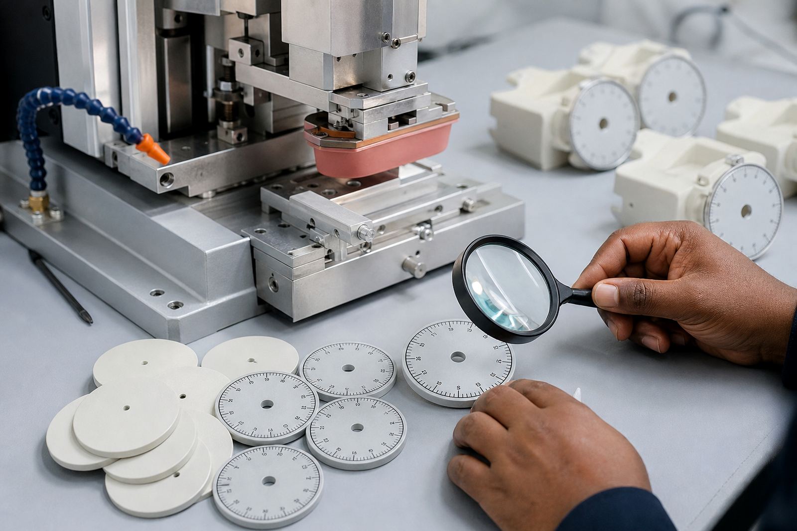
Before moving to a full production run, we made adhesion test samples and trial sample runs. This stage matters because pad printing can look right at first glance but still need adjustment in ink flow, pad hardness, transfer pressure or drying time. We made changes before release so the client would not get avoidable rejects later.
- Artwork preparation for polarity and part ID marks
- Logo redraw style cleanup where line clarity needed tightening
- Print area planning to suit the shell shape
- Colour matching for the required contrast against the part colour
- Adhesion test samples to confirm the mark would hold under handling
By the end of this stage, we had a repeatable image and a setup the client could sign off with confidence. It was not about making the mark simply visible, but making it practical for production use and easy to repeat on later batches.
Fixture making and print control in the run
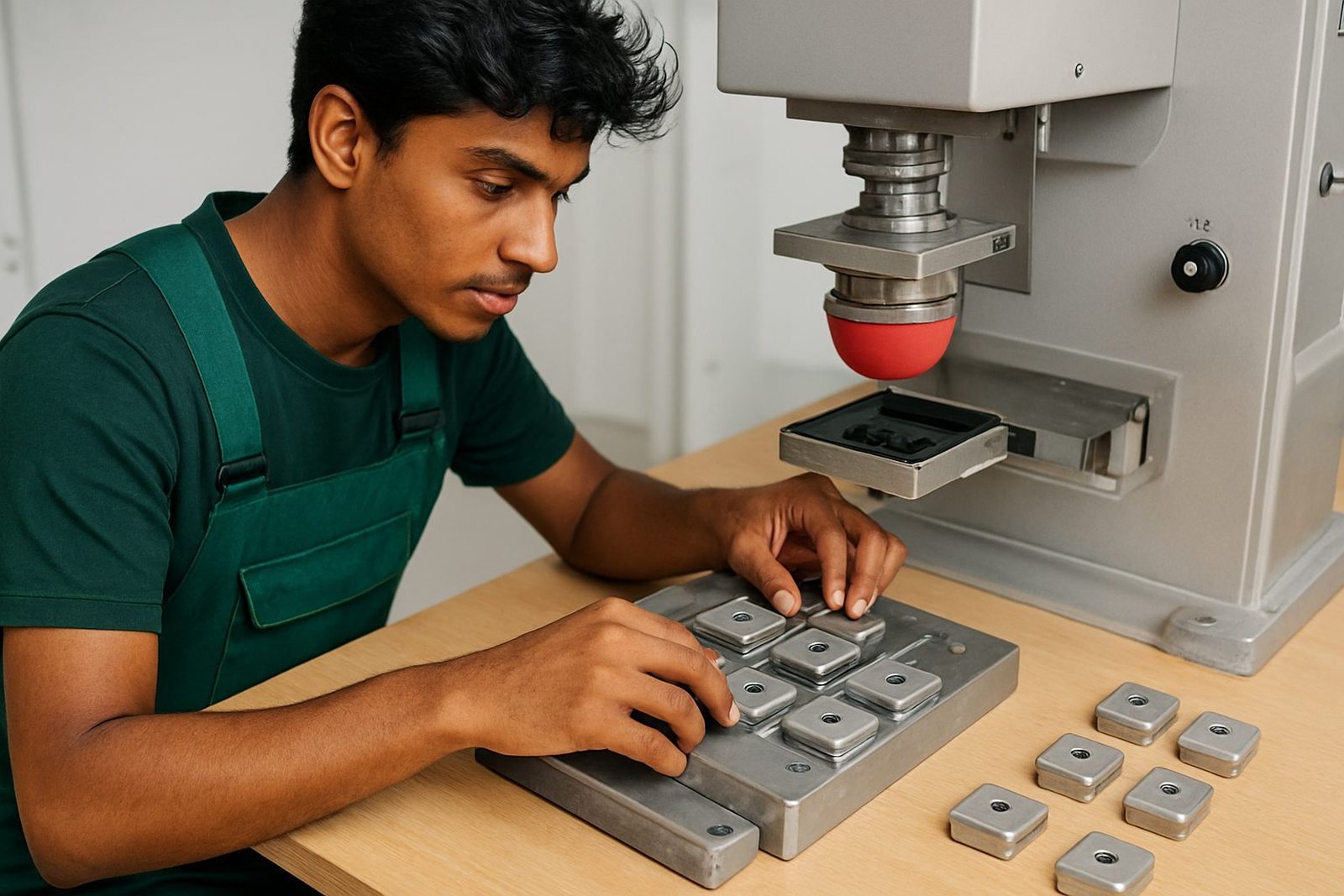
Once the image was approved, we made fixtures to hold the connector shells in a fixed position during printing. This is essential on small electronic parts because even a slight movement can shift the mark off centre or distort the orientation. The fixture also helps keep operator handling consistent, which lowers the risk of smudges and damaged parts.
We then completed the machine setup and chose the curing method that matched the ink and the plastic shell material. The cure had to be strong enough for handling, but not so harsh that it changed the part finish. We also set the rerun job control so any later reorders could be matched to the same approved settings instead of starting from scratch each time.
- Fixture making for stable part location
- Machine setup with consistent pad transfer settings
- Curing method selection to suit the substrate and ink system
- Rerun job control for repeat batches
- Dispatch packing so finished parts stayed protected in transit
The production run itself was straightforward once the setup was locked in. We monitored the first pieces closely, checked mark position and kept an eye on cure consistency. Where needed, we corrected small variations early, which saved time later in the batch.
Timeline from enquiry to finished shells
This timing worked because the client wanted controlled output rather than a rushed turnaround. In electronic manufacturing, a short delay at the setup stage is often cheaper than reworking an entire batch after the fact. We kept the process tight but not hurried, which gave the client a clear decision point before the main run.
For a project like this, that three week window is usually enough if the artwork is ready and the part geometry is settled. If the print area changes or the shell material changes, we would plan for extra sample time.
Results on the finished connector shells
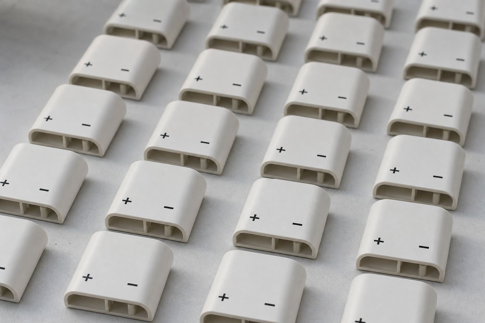
The finished connector shells carried the polarity and part identification marks cleanly, with good edge definition and steady placement from part to part. The prints were suitable for handling in the contractor's workflow and provided the visual identification they needed during assembly and downstream use.
What the client valued most was consistency. The marks matched across the batch, the shells stayed readable after curing, and the setup could be repeated for future production without having to rebuild the whole job each time. That matters when a manufacturer is trying to keep production moving and avoid mixed parts or placement errors.
We also gave the client a production route they could return to for the same shell family. That means future batches can follow the same artwork, plate and fixture settings, making repeat work simpler and less prone to drift.
- Clear polarity identification on a small print area
- Repeatable placement on moulded connector shells
- Adhesion suited to normal handling and assembly
- Reusable setup for future production runs
Kept for the next batch
If the same client came back with another batch, we would follow the same route: review the artwork, confirm the shell colour and print area, check whether the material or mould finish has changed, and then run fresh adhesion samples before full production. That approach keeps the job controlled and avoids surprises.
We would also keep the fixture design on file and review whether any small changes are needed for wear or part variation. On repeated electronics work, those small checks are worth it. A shell may look identical from one mould run to the next, but even slight changes in surface finish can affect ink laydown.
For customers across Durban, Johannesburg, Cape Town, Pretoria and Gqeberha, this is the kind of pad printing support we provide from Pinetown. It is practical, local and built around the realities of manufacturing, not guesswork.
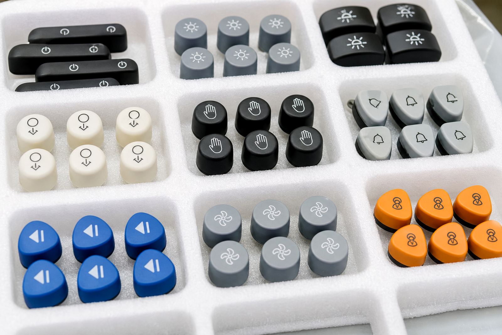
If you need polarity marks, part ID, logo prints or other identification on medical or electronic parts, we can quote the setup properly and work from samples, not assumptions.
Run details
| Project | Prospecton Connector Shells |
|---|---|
| Client type | Electronics contractor |
| Town | Prospecton, Durban |
| Process | Pad printing on moulded connector shells |
| Timeline | 3 weeks from enquiry to finished dispatch |
| Marks | Polarity symbols and part identification |
| Base | Westmead, Pinetown |