
Why traceability marks fail on small parts
On a large housing, a serial number has room to breathe. On a clamp, connector, cap, sensor body or injector component, that same information has to fit into a very small print area without crowding the edge or falling into a curve. If the mark is squeezed, the result is often a blurred code, weak contrast, or text that disappears once the part is cleaned or handled at line speed.
Pad printing suits this work because a silicone pad can pick up fine detail from an etched plate and transfer it onto uneven or recessed surfaces. The challenge is not only getting the ink on the part, but planning the mark so it remains legible after curing, wiping and use. For medical and electronic components, a traceability field must be designed with the actual part geometry in mind, not copied from a larger label format.
- Keep the most important identifier first, such as a batch code or serial number.
- Allow margin around the mark so the edges do not break up on curved surfaces.
- Choose characters that stay clear when scaled down.
What should sit in the layout and what can be left out
A good traceability layout is practical. It carries the minimum information needed for internal control, incoming inspection and job tracking without overcrowding the part. In many cases the layout includes a part code, batch number, date code, cavity reference or a small company mark. The fields must be arranged so operators can print them consistently, and so the information remains readable after assembly.
For some customers, the temptation is to fit every detail into one area. That usually causes trouble. Smaller marks need a simple hierarchy, with the most critical field placed where the eye finds it first. If there are multiple lines, they should be separated cleanly and matched to the available print area. Customers remain responsible for their own device compliance, so the layout must support their internal and regulatory requirements rather than guessing at them.
- Use one primary identifier and only add secondary fields where space allows.
- Avoid thin fonts that fill in during plate exposure or ink transfer.
- Check whether the mark will be viewed by people, scanners or both.
Building the mark around the part, not the other way around
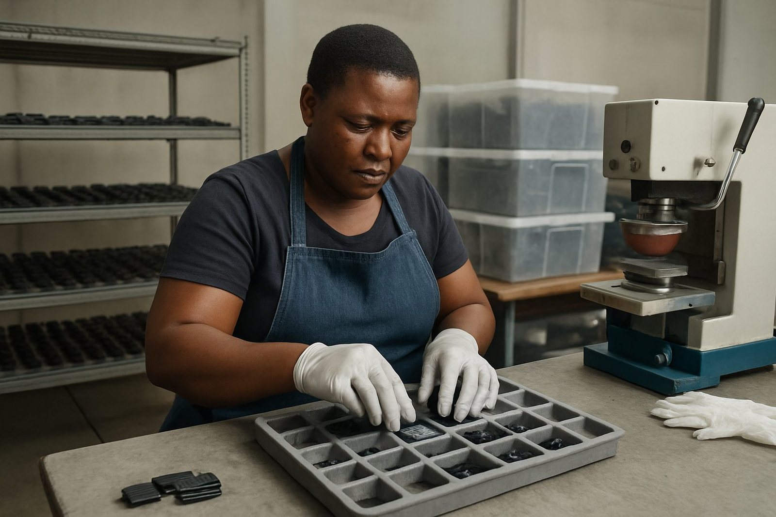
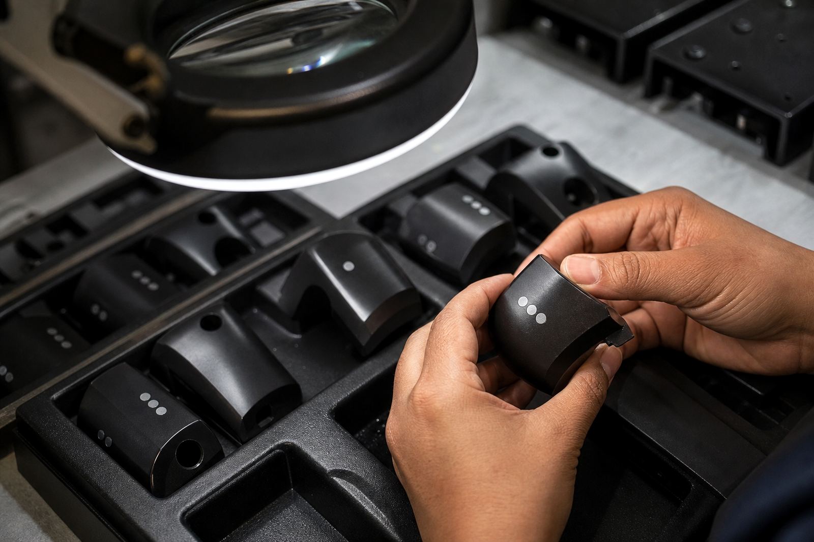
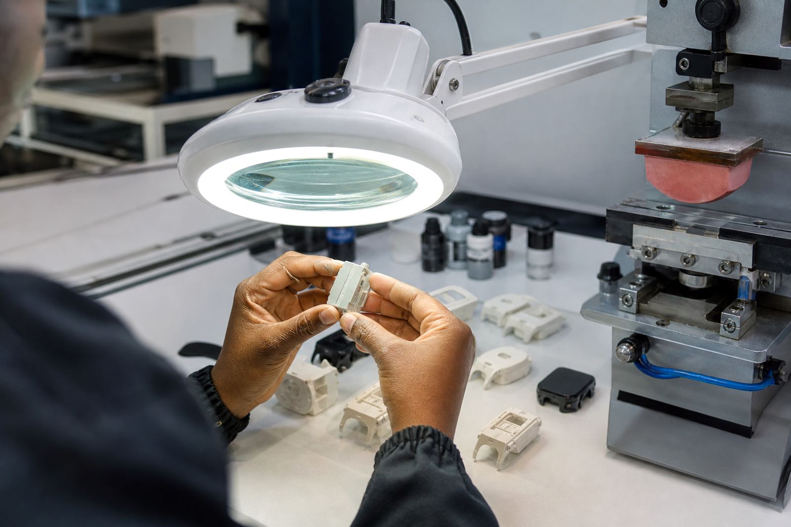
Every part behaves differently under the pad. A flat cap, a narrow medical housing and a connector shell do not take ink in the same way. Curved surfaces may distort the mark slightly, while textured plastics can reduce edge sharpness. That is why layout planning starts with the physical sample, the print area and the direction in which the part is presented to the machine.
At our Westmead, Pinetown base, we often see jobs where the information is technically correct but placed too close to a rib, gate mark or mould seam. The fix is usually simple: move the mark a few millimetres, adjust the plate artwork, or split the content over two lines. On a component only a few centimetres long, that small change can make the difference between a clean traceability mark and a rework run.
A local example is a Durban electronics supplier sending in small plastic housings for batch identification. The first layout looked fine on screen, but once tested on the part the code sat across a shallow curve and one digit lost definition. By shifting the field and reducing the line count, the mark became easier to read and the operator had a better repeatable position for the pad. Simple change, better control.
Ink, curing and handling affect whether the layout holds up
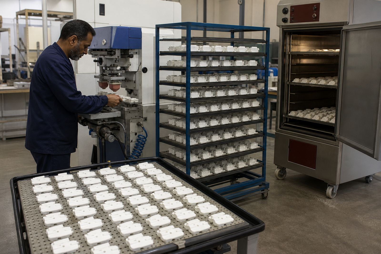
The layout cannot be separated from the printing process. Even a well planned mark can fail if the ink does not bond to the substrate or if the curing method is not matched to the part. Some plastics need careful surface preparation, while others print well but need controlled drying before packing. Heat sensitive parts may not suit aggressive curing, so the choice has to suit the material and the production flow.
We often recommend trial sample runs before full production. These show whether the planned layout holds its clarity after curing, stacking and light abrasion. If the part will be wiped during assembly, or handled in a humid coastal environment, the mark should be checked for scuffing and colour loss. In Durban and the coastal belt, humidity can affect drying times, so a layout that looks clean on day one must still remain legible after the part has settled.
- Test the mark after curing, not only straight off the pad.
- Check adhesion on the actual production material, not just a similar sample.
- Confirm that the layout survives the way the part is packed, stacked and moved.
How to make traceability easier for operators
Operator friendly layout saves time on the floor. If the mark is hard to find, awkward to orientate or inconsistent between parts, the line slows down. Good layout planning gives the setter clear reference points and keeps the same print position from job to job.
Practical layout choices include fixed alignment marks, clear spacing between fields and a print area that can be fixtured repeatably. Fixture making and trial runs help here because they show whether the part sits consistently in the same place for every impression. If the traceability mark is intended for later visual checks, make sure the layout has enough contrast and enough blank space around it for quick reading on the bench.
- Build in a repeatable orientation point for the operator.
- Keep the print zone away from clamp points and moving edges.
- Use the same layout format across related part families where possible.
From artwork to rerun control, the layout has to stay stable
Once a traceability mark is approved, it should stay stable through reruns. That means the artwork, plate exposure, plate etching and print area planning all need to be controlled so the same field lands in the same place each time. If a job returns months later and the layout has drifted, the customer can face confusion in stock control and internal tracking. Consistency matters just as much as sharpness.
At PadPrinters Medical in Westmead, Pinetown, our work for manufacturers across South Africa often starts with artwork preparation and logo redraws, then moves into plate setup, sample runs and rerun job control. For traceability marks, the aim is straightforward: keep the information clear, keep the layout repeatable, and make sure the part can be printed without forcing the operator to fight the geometry. That is what makes a small mark useful in the real world, whether the parts are going to Johannesburg, Cape Town, Pretoria or Gqeberha.
Dispatch packing then needs to protect that consistency. If printed parts arrive scuffed or mixed by batch, the best layout in the world will not help. Good traceability starts with the mark, but it only works when the whole print and packing process is managed as one job.