
Readable marking for electronics parts
On electronic housings, control panels, battery covers and moulded inserts, the marking often does more than carry a logo. It can show button functions, polarity, warnings, part codes, orientation marks and serial areas that help production and support teams work faster. If the print is faint, the wrong colour or placed off centre, the part can look poor and cause problems later on the line.
Pad printing is widely used for these jobs because a silicone pad can pick up ink from an etched plate and transfer it onto curved, recessed or uneven surfaces with good repeatability. That matters on small enclosures, switch bezels and textured plastics where flatbed printing is not practical. In Pinetown and Westmead, many manufacturers need short runs, repeat runs and quick artwork updates, especially when a housing changes after a tooling revision or a customer asks for a bilingual label.
For electronics work, the best results usually come from careful preparation before the first print. That includes checking the plastic type, surface finish, ink compatibility and the expected wear on the part. A nice print is not enough if the mark rubs off during assembly or cleaning, so the process needs to be planned around the real use of the component.
Typical legends, icons and branding on plastic enclosures
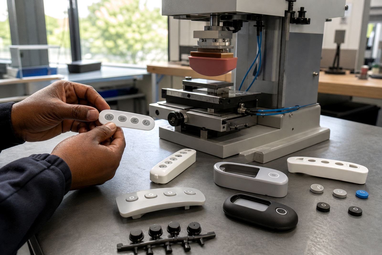
Most electronics marking jobs fall into a few familiar groups. The print may need to carry a model code, warning triangle, power symbol, socket indicator, direction arrow or simple logo. On consumer and industrial parts the layout is often small, so the artwork must be tidy and easy to read at the final size, not only on a computer screen.
Good print area planning makes a real difference. A small icon that sits too close to a mould line or screw boss can distort, and a thick font can fill in when the part has a slight curve. That is why artwork redraws and plate preparation are often part of the job, not an extra. If a customer sends a low resolution file, it may need cleanup before plate exposure so the edges print sharply.
- Button legends and function labels for control panels
- Polarity marks, caution symbols and directional arrows
- Brand logos and part identification codes
- Plug, socket and switch position indicators
- Batch references and service marks for internal use
On black housings the most common request is high contrast white or grey print. On white or light parts, a darker ink may be used for readability. Colour matching matters too, especially where a logo has to sit with existing moulded colours or where a client wants a very specific shade across multiple parts.
How pad printing is set up for clean repeat runs
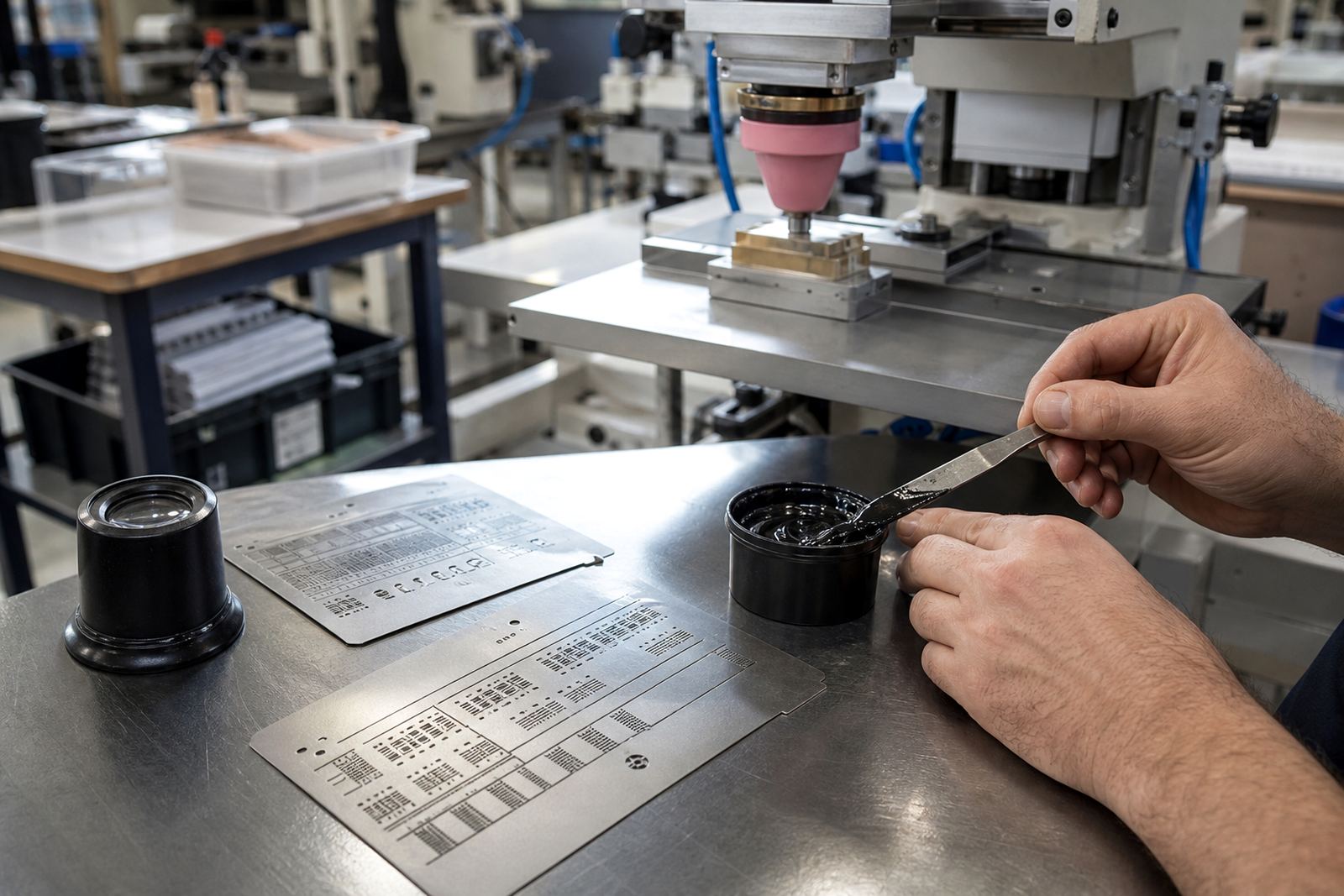
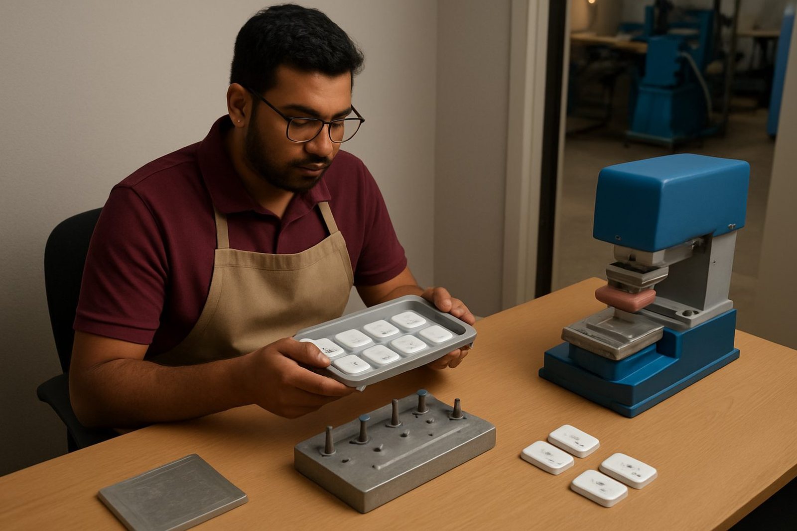
A reliable pad print starts with the plate, the ink and the fixture. The plate carries the etched image, the ink fills the etched areas, and the silicone pad lifts and transfers the image to the part. Each stage has to be consistent. If the fixture lets the part move even slightly, the print can sit skew or double up at the edges.
With a proper setup, the team will usually test the part before production starts. That can include adhesion test samples, trial sample runs and then a controlled rerun once the artwork and placement are confirmed. If the housing has texture, compound curves or shallow recesses, the pad shape and print pressure need adjustment. There is no single setting that suits every job of this kind.
- Artwork Preparation to clean up logos and legends
- Plate Exposure and Plate Etching for accurate image transfer
- Fixture Making for stable placement during printing
- Trial Sample Runs before full production
- Rerun Job Control when follow-up jobs need the same finish
At PadPrinters Medical in Westmead, Pinetown, the focus is on repeatability. That matters to manufacturers in Durban, Johannesburg, Cape Town, Pretoria and Gqeberha who need the same mark months later on a replacement order. When a component is part of a larger assembly, even a small shift in position can affect how the finished product looks and fits.
Ink choice, curing and wear resistance in real use
Electronics parts do not all live the same life. Some sit inside a protected cabinet, while others are handled daily, cleaned with alcohol based wipes or exposed to heat near motors and chargers. The ink system has to suit that use. Certain plastics need stronger surface preparation or a specific curing method so the print bonds properly and does not lift after the first few weeks.
Curing is not just a final step, it is part of the print quality. Some jobs need air drying, others need heat curing or a chosen curing method matched to the substrate and production speed. If the curing is rushed, the print may look good in the tray but fail later on the assembly line. In a humid Durban environment this can be more noticeable, especially when parts are packed soon after printing and stacked close together.
For manufacturers, the practical checks are simple. Does the print stay clear after handling? Does the colour stay even across the batch? Does the mark survive the cleaning process used in the factory? These are the questions that matter before a job moves into regular production.
Planning the print around the part and the assembly line
Good electronics marking starts with the part itself. A housing may have ribs, snap fits, vents, mould lines and textured zones that all affect where the print can sit. The best location is not always the most visible one. It has to be accessible for printing, readable after assembly and clear of areas that get clamped, trimmed or sealed.
That is why practical print area planning is so important. A marking that works on a sample can still fail in production if the fixture is not holding the part the same way every time. Small changes to wall thickness or surface shape can also change the final result. For customers in New Germany, Westville and the wider Durban manufacturing area, it helps to review the part with the print supplier before the order moves forward.
Common issues that can be avoided early include:
- Printing too close to a curved edge or mould line
- Using text that becomes too small at final size
- Placing marks where the assembly tool will rub them
- Choosing a colour that lacks contrast on the substrate
- Skipping a sample run on a new plastic batch
When these details are handled properly, the finished part looks more professional and the production team spends less time sorting out rejects.
A Durban example for national supply
A common local example is a small electronics enclosure produced in Westmead for distribution across South Africa. The part may need a company logo on the front, a power icon near one switch, a warning mark on the back and a part code on the underside. The enclosure might be white ABS, black polypropylene or another moulded plastic that needs the print to sit cleanly over a slightly curved face.
In that kind of job, the process would normally begin with artwork redraws if the supplied file is not suitable for plate work. Then the team would confirm print area planning, make the plate, run a few sample prints and check the finish after curing. If the first trial shows the logo needs to move 2 to 3 mm to clear a rib, that is adjusted before dispatch. It saves time later and keeps the repeat job consistent.
PadPrinters Medical supports manufacturers from Pinetown and Durban to Johannesburg, Pretoria, Cape Town and Gqeberha through one enquiry process on the contact page. The service areas include Pinetown Printing Support, Durban Manufacturers, Johannesburg Supply, Pretoria Supply, Cape Town Supply, Gqeberha Supply, New Germany Support and Westville Support, with dispatch packing arranged for finished parts that must travel well. Customers remain responsible for their own device compliance, but the marking itself can be planned to suit the product and its production needs.